Dear readers,
We have prepared for you a list of the most important news in the VXelements, VXinspect and VXmodel programs. You can download the new version of the VXelements 8 program (VXinspect and VXmodel are part of the installation) after logging in to the Creaform support page. We hope that most of the news will make your work easier and speed up the whole process from scanning to data output.
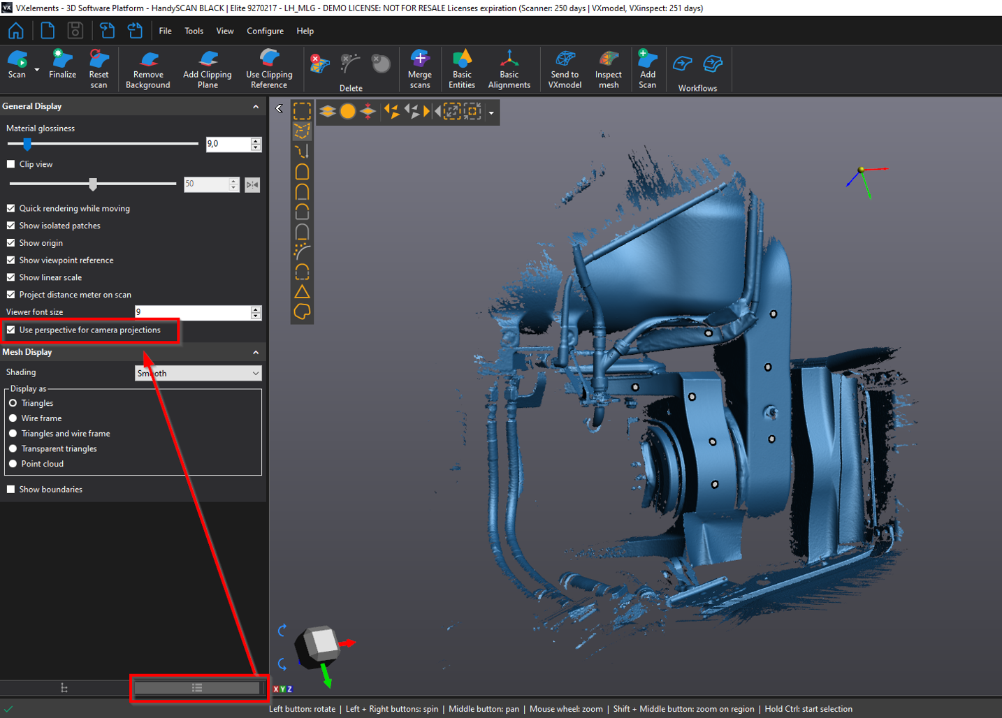
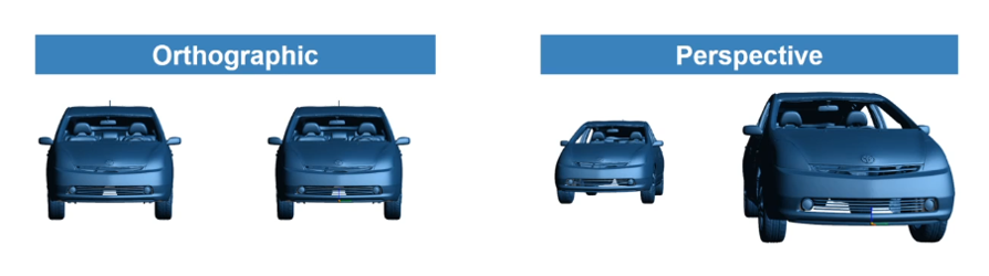
In the "Display" tab, you can now choose whether you want to display objects in the graphic area orthographically or in perspective. After installing the program, the perspective view is turned on by default. In this view, 3D data appears more realistic and it is easier to view closed areas.
 |
 |
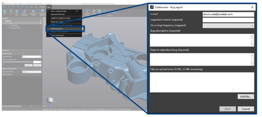
Users can now report non-standard VXelements behavior to technical support directly from VXelements. All you have to do is describe the problem, attach, for example, a picture of where the error occurs and send it. Technical support is analyzing the problem and will contact the sender of this message.
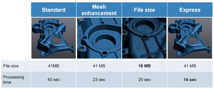
Thanks to new polygon mesh recalculation algorithms, the user can better influence the final shape of the exported STL file. We now have the following options:
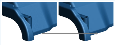
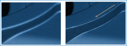
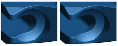
Before saving the final polygon mesh after 3D scanning, the user now has the option to choose how the mesh should look. The recalculation of all captured images is adjusted according to the desired orientation, and the user subsequently receives the final polygon mesh according to his preferences.
The new version of the VXelements program enables the users of the MetraSCAN 3D measuring system the following new functions to speed up, facilitate and simplify the work:
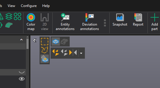
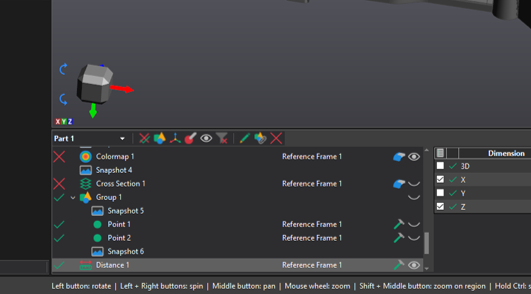
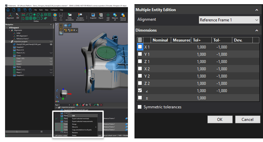
Reorganization of the graphical layout of the QA application. Greater clarity and simplicity of work.
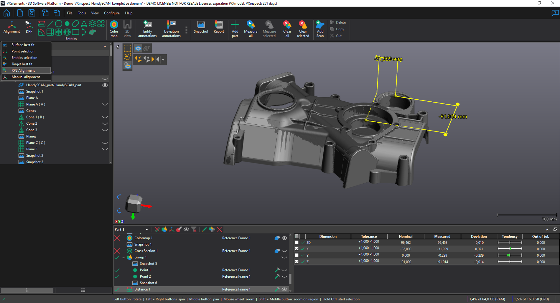
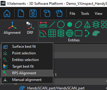
New alignment method - RPS. A long awaited feature. Which will be welcomed by many customers and future clients.
The user can now easily choose, using quick icons, whether he wants to select data on a scan or a CAD model.
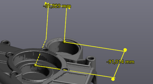
All created dimensions can now be moved and manipulated at will.
In the new dialog box, you can quickly change the requirements for the evaluation of elements. We can change controlled dimensions and adjust tolerances quickly.
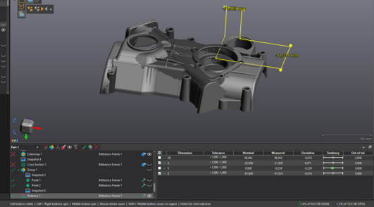
It is now possible to search the inspection tree for specific commands based on filters (e.g. did not pass tolerance...). Individual elements can also be grouped into folders to create a clear inspection process.
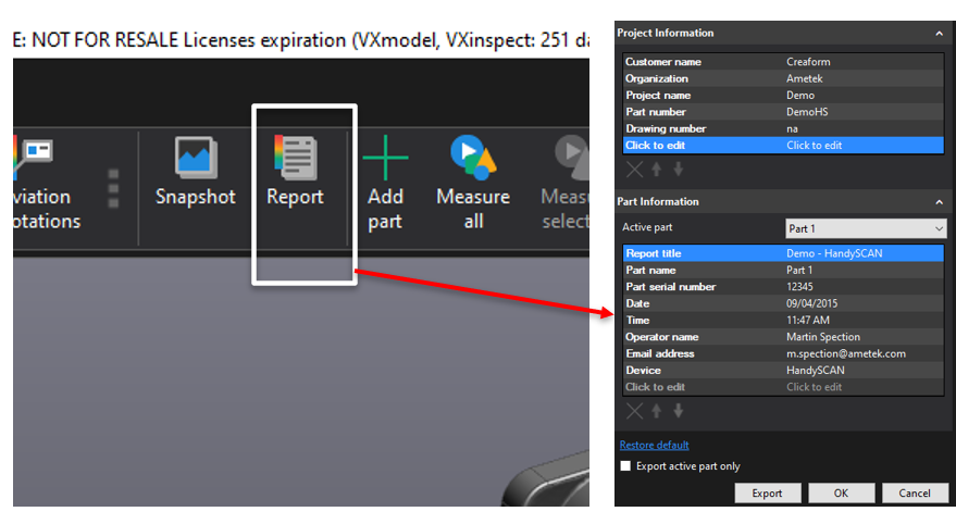
In version VXinspect 8, you can add your own editable fields to the headers of inspection reports. The user thus has the opportunity to add the necessary information to the reports.
In the inspection tree, it is possible to select multiple identical entities at once with the CTRL keyboard and thus adjust the tolerances at once.
In VXmodel, just select the surface of the pipe and the program will automatically generate the center route for you in the 3D sketch. You can then smooth out this route in the CAD modeler and use it for a new sweep.

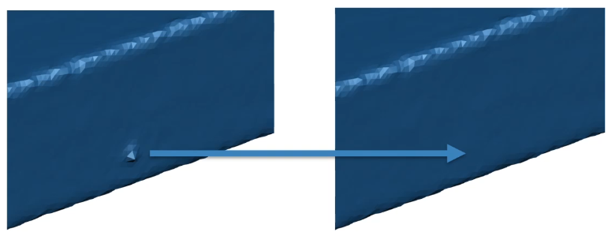
Local deformations can be smoothed out with sandpaper. Just choose the intensity and size of the affected area. Your resulting scan can be perfect without any defects.
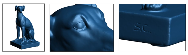
With this tool, you can highlight certain areas on the scan, or, conversely, add material. The shape of the scan can thus be easily changed and ideal results for 3D printing can be achieved.
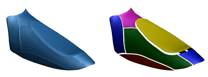
The user can draw the circuits of individual parts on the scan. The program then divides the network into individual areas according to the drawn profiles. It is not necessary to cut individual areas one by one. Now just draw the borders of the areas and VXmodel will separate all the areas into one. During this operation, you can also directly enter the names of individual parts, and orientation in the newly created networks is thus simple.


Headquarters
SolidVision, s.r.o
Josefy Faimonová 11a
628 00 Brno
CIN: 26280442
VAT: CZ26280442
Prague branch
Zábehlický castle
Behind Potok 46/4
Runaway
106 00 Prague 10


